Sed1520 Driver C
Introduction. Recently I bought a LCD graphic display from Sure Eletronics JCG12232A02-01, product name RDE-LM26111, this LCD use the famous SED1520.

Has anyone there same sample code to start with graphic LCD
Just read the online doc and update any graphics lcd.
I have some code. But I can t remember how complete or functional it is.
This is for the epson sed 1335. should be close.
/////////////////////////////////////////////////////////////////////////
//// c: program files PICC drivers LCD_epson1335.c ////
//// This file contains drivers for using a Epson SED1335 controller ////
//// in parallel/8080 intel mode. The SED1335 is 320 pixles across ////
//// and 240 pixels down. The driver treats the upper left pixel 0,0////
//// ////
//// glcd_init mode ////
//// Must be called before any other function. ////
//// - mode can be ON or OFF to turn the LCD on or off ////
//// glcd_pixel x,y,color ////
//// Sets the pixel to the given color. ////
//// - color can be ON or OFF ////
//// glcd_line x1,y1,x2,y2,color ////
//// Draws a line from the first point to the second point ////
//// with the given color. ////
//// glcd_rect x1,y1,x2,y2,fill,color ////
//// Draws a rectangle with upper left point x1,y1 and lower ////
//// right point x2,y2. ////
//// - fill can be YES or NO ////
//// glcd_bar x1,y1,x2,y2,width,color ////
//// Draws a bar wide line from the first point to the ////
//// second point. ////
//// - width is the number of pixels wide ////
//// - color is ON or OFF ////
//// glcd_circle x,y,radius,fill,color ////
//// Draws a circle with center at x,y ////
//// glcd_text57 x,y,textptr,size,color ////
//// Write the null terminated text pointed to by textptr with ////
//// the upper left coordinate of the first character at x,y. ////
//// Characters are 5 pixels wide and 7 pixels tall. ////
//// - size is an integer that scales the size of the text ////
//// Note - The given text is character wrapped. If this ////
//// function is used on a different size display, then change ////
//// the GLCD_COL define appropriately. ////
//// glcd_fillScreen color ////
//// Fills the entire LCD with the given color. ////
define GLCD_COL 128 // Used for text wrapping by glcd_text57 function and sanity check
define GLCD_ROW 64 // Used for text wrapping by glcd_text57 function and sanity check
//LCD_CS VAR PORTA.1 Chip select BAR
//LCD_RST VAR PORTA.2 Reset BAR
//LCD_A0 VAR PORTA.3 1 Data 0 Command
//LCD_WR VAR PORTA.4 1 Read 0 Write
//LCD_RD VAR PORTA.5 Enable
//LCD_DAT VAR PORTD Data Pin
BOOLEAN unused0; // A0 unused
BOOLEAN cs_bar; // A1 Chip select active low
BOOLEAN reset_bar; // A2 Reset active low
BOOLEAN A0; // A3 Data/Instruction 1 data 0 Instruction
BOOLEAN w_bar; // A4 Write bar active low
BOOLEAN r_bar; // A5 Read bar active low
BOOLEAN unused1; // A6 Unused
BOOLEAN unused2; // A7 Unused
int unused3 : 8; // PortB waisted some bits/bytes for clarity
int unused4 : 8; // PortC waisted some bits/bytes for clarity
int data : 8; // PortD Data bus
define set_tris_lcd x set_tris_a 0 ;set_tris_B 0 ;set_tris_d x
byte LCD 5 //note: no semicolin 5 A0 on a 16F877A
BOOLEAN glcd_pixel unsigned int x,unsigned int y, int1 color ;
void glcd_writeByte BYTE chip, BYTE data ;
void glcd_fillScreen int1 color ;
const BYTE TEXT 51 5 0x00, 0x00, 0x00, 0x00, 0x00, // SPACE
0x00, 0x00, 0x5F, 0x00, 0x00, //.
0x00, 0x03, 0x00, 0x03, 0x00, //
0x14, 0x3E, 0x14, 0x3E, 0x14, //
0x24, 0x2A, 0x7F, 0x2A, 0x12, //
0x43, 0x33, 0x08, 0x66, 0x61, //
0x36, 0x49, 0x55, 0x22, 0x50, //
0x00, 0x05, 0x03, 0x00, 0x00, //
0x00, 0x1C, 0x22, 0x41, 0x00, //
0x00, 0x41, 0x22, 0x1C, 0x00, //
0x14, 0x08, 0x3E, 0x08, 0x14, //
0x08, 0x08, 0x3E, 0x08, 0x08, //
0x00, 0x50, 0x30, 0x00, 0x00, //,
0x08, 0x08, 0x08, 0x08, 0x08, // -
0x00, 0x60, 0x60, 0x00, 0x00, //.
0x20, 0x10, 0x08, 0x04, 0x02, // /
0x3E, 0x51, 0x49, 0x45, 0x3E, // 0
0x04, 0x02, 0x7F, 0x00, 0x00, // 1
0x42, 0x61, 0x51, 0x49, 0x46, // 2
0x22, 0x41, 0x49, 0x49, 0x36, // 3
0x18, 0x14, 0x12, 0x7F, 0x10, // 4
0x27, 0x45, 0x45, 0x45, 0x39, // 5
0x3E, 0x49, 0x49, 0x49, 0x32, // 6
0x01, 0x01, 0x71, 0x09, 0x07, // 7
0x36, 0x49, 0x49, 0x49, 0x36, // 8
0x26, 0x49, 0x49, 0x49, 0x3E, // 9
0x00, 0x36, 0x36, 0x00, 0x00, // :
0x00, 0x56, 0x36, 0x00, 0x00, // ;
0x08, 0x14, 0x22, 0x41, 0x00, //
0x14, 0x14, 0x14, 0x14, 0x14, //
0x00, 0x41, 0x22, 0x14, 0x08, //
0x02, 0x01, 0x51, 0x09, 0x06, //.
0x3E, 0x41, 0x59, 0x55, 0x5E, //
0x7E, 0x09, 0x09, 0x09, 0x7E, // A
0x7F, 0x49, 0x49, 0x49, 0x36, // B
0x3E, 0x41, 0x41, 0x41, 0x22, // C
0x7F, 0x41, 0x41, 0x41, 0x3E, // D
0x7F, 0x49, 0x49, 0x49, 0x41, // E
0x7F, 0x09, 0x09, 0x09, 0x01, // F
0x3E, 0x41, 0x41, 0x49, 0x3A, // G
0x7F, 0x08, 0x08, 0x08, 0x7F, // H
0x00, 0x41, 0x7F, 0x41, 0x00, // I
0x30, 0x40, 0x40, 0x40, 0x3F, // J
0x7F, 0x08, 0x14, 0x22, 0x41, // K
0x7F, 0x40, 0x40, 0x40, 0x40, // L
0x7F, 0x02, 0x0C, 0x02, 0x7F, // M
0x7F, 0x02, 0x04, 0x08, 0x7F, // N
0x3E, 0x41, 0x41, 0x41, 0x3E, // O
0x7F, 0x09, 0x09, 0x09, 0x06, // P
0x1E, 0x21, 0x21, 0x21, 0x5E, // Q
0x7F, 0x09, 0x09, 0x09, 0x76 ;// R
const BYTE TEXT2 44 5 0x26, 0x49, 0x49, 0x49, 0x32, // S
0x01, 0x01, 0x7F, 0x01, 0x01, // T
0x3F, 0x40, 0x40, 0x40, 0x3F, // U
0x1F, 0x20, 0x40, 0x20, 0x1F, // V
0x7F, 0x20, 0x10, 0x20, 0x7F, // W
0x41, 0x22, 0x1C, 0x22, 0x41, // X
0x07, 0x08, 0x70, 0x08, 0x07, // Y
0x61, 0x51, 0x49, 0x45, 0x43, // Z
0x00, 0x7F, 0x41, 0x00, 0x00, //
0x02, 0x04, 0x08, 0x10, 0x20, //
0x00, 0x00, 0x41, 0x7F, 0x00, //
0x04, 0x02, 0x01, 0x02, 0x04, //
0x40, 0x40, 0x40, 0x40, 0x40, // _
0x00, 0x01, 0x02, 0x04, 0x00, //
0x20, 0x54, 0x54, 0x54, 0x78, // a
0x7F, 0x44, 0x44, 0x44, 0x38, // b
0x38, 0x44, 0x44, 0x44, 0x44, // c
0x38, 0x44, 0x44, 0x44, 0x7F, // d
0x38, 0x54, 0x54, 0x54, 0x18, // e
0x04, 0x04, 0x7E, 0x05, 0x05, // f
0x08, 0x54, 0x54, 0x54, 0x3C, // g
0x7F, 0x08, 0x04, 0x04, 0x78, // h
0x00, 0x44, 0x7D, 0x40, 0x00, // i
0x20, 0x40, 0x44, 0x3D, 0x00, // j
0x7F, 0x10, 0x28, 0x44, 0x00, // k
0x00, 0x41, 0x7F, 0x40, 0x00, // l
0x7C, 0x04, 0x78, 0x04, 0x78, // m
0x7C, 0x08, 0x04, 0x04, 0x78, // n
0x38, 0x44, 0x44, 0x44, 0x38, // o
0x7C, 0x14, 0x14, 0x14, 0x08, // p
0x08, 0x14, 0x14, 0x14, 0x7C, // q
0x00, 0x7C, 0x08, 0x04, 0x04, // r
0x48, 0x54, 0x54, 0x54, 0x20, // s
0x04, 0x04, 0x3F, 0x44, 0x44, // t
0x3C, 0x40, 0x40, 0x20, 0x7C, // u
0x1C, 0x20, 0x40, 0x20, 0x1C, // v
0x3C, 0x40, 0x30, 0x40, 0x3C, // w
0x44, 0x28, 0x10, 0x28, 0x44, // x
0x0C, 0x50, 0x50, 0x50, 0x3C, // y
0x44, 0x64, 0x54, 0x4C, 0x44, // z
0x00, 0x08, 0x36, 0x41, 0x41, //
0x00, 0x00, 0x7F, 0x00, 0x00, //
0x41, 0x41, 0x36, 0x08, 0x00, //
0x02, 0x01, 0x02, 0x04, 0x02 ;//
// - - - - - - - - - - - - - - - - - - - - - - - - - - - - - - - - - - - - - //
// Purpose: Initialize a graphic LCD. This must be called before any
// other glcd function is used.
// Inputs: The initialization mode
// OFF - Turns the LCD off
// ON - Turns the LCD on
set_tris_lcd 0x00 ; //All outputs
LCD.A0 0;LCD.r_bar 1;LCD.w_bar 1;
LCD.reset_bar 0; //reset state
glcd_writeByte 0, 0xE2 ; // ;reset display
glcd_writeByte 0, 0xA2 ; // ;lcd bias 1_9
glcd_writeByte 0, 0xA1 ; // ;normal
//glcd_writeByte 0, 0x DI ; // ;mirror image
glcd_writeByte 0, 0xC0 ; // ;common_output_normal upside dnw mirror
glcd_writeByte 0, 0x27 ; // ;v5 resistor ratio perhaps 24
glcd_writeByte 0, 0x81 ; // ;electronic volume set
glcd_writeByte 0, 0x10 ; // ;electronic volume init
glcd_writeByte 0, 0x2F ; // ;power control
glcd_writeByte 0, 0x40 ; // ;start line set
glcd_writeByte 0, 0xB0 ; // ;page address set
glcd_writeByte 0, 0x10 ; // ;column address high
glcd_writeByte 0, 0x00 ; // ;column address low
glcd_writeByte 0, 0xAF ; // ;turn on display
glcd_writeByte 0, 0xA4 ; // ;NOT all on display NORMAL
glcd_writeByte 0, 0xA6 ; // ;normal video
//glcd_writeByte 0, 0x A7 ; // ;reverse video
glcd_writeByte 0, 0xAF ; // Turn the display ON
glcd_writeByte 0, 0xAE ; // Turn the display OFF
fprintf debug, LCD Status after init x n r, d1 ;
set_tris_lcd 0xFF ; //Port D tristate
// Purpose: Turn a pixel on a graphic LCD on or off
// Inputs: x - the x coordinate of the pixel
// y - the y coordinate of the pixel
// color - ON or OFF
// Output: 1 if coordinate out of range, 0 if in range
BOOLEAN glcd_pixel unsigned int x,unsigned int y, int1 color
// fprintf debug, Pixel at d, d n r, x, y ;
// fprintf debug, Pixel at U, U , x, y ;
if x GLCD_COL x 0 return 1 ; // Check for valid x
if y GLCD_ROW y 0 return 1 ; // Check for valid y
glcd_writeByte 0, y 3 0xB0 ; // Set the page that is y/8 0xB0
glcd_writeByte 0, x 4 0x10 ; // Set the COL address, upper 4 bits
// fprintf debug, Upper x n r, x 4 0x10 ;
glcd_writeByte 0, x 0xF ; // Set the COL address, lower 4 bits
// fprintf debug, Lower x n r, x 0xF ;
glcd_writeByte 0, 0xE0 ; // fctn 12 Read/Modify/Write..ie:don t inc on a read
glcd_writeByte 0, 0xEE ; // fctn 13 END..ie:Restart inc on a read
bit_set data, y 8 ; // Turn the pixel data bit on or off
glcd_writeByte 1, data ; // Write new data back to LCD this will inc ptr
// Purpose: Write a byte of data or instruction to LCD
// Inputs: DI - 1 data 0 Instruction
// data - the byte of data to write
void glcd_writeByte int1 DI, BYTE data
// fprintf debug, write byte n r ;
// Purpose: Reads a byte of data from the current location
// Ouputs: A byte of data read from the LCD
BYTE data; // Stores the data read from the LCD
set_tris_lcd 0xFF ; //Port D inputs
LCD.r_bar 0; //Read FALSE READ
LCD.r_bar 0; //Read Real READ
return data; //Return the read data
// Purpose: Reads status of LCD
// Ouputs: A byte of data read from the chip
BYTE data; // Stores the data read from the LCD
set_tris_lcd 0xFF ; // Port D inputs
return data 4 ; //Return status
// Purpose: Draw a line on a graphic LCD using Bresenham s
// line drawing algorithm
// Inputs: x1, y1 - the start coordinate
// x2, y2 - the end coordinate
void glcd_line int x1, int y1, int x2, int y2, int1 color
signed int x, y, addx, addy, dx, dy;
// Purpose: Draw a rectangle on a graphic LCD
// fill - YES or NO
// Dependencies: glcd_pixel, glcd_line
void glcd_rect int x1, int y1, int x2, int y2, int fill, int1 color
int y, ymax; // Find the y min and max
for ; y ymax; y // Draw lines to fill the rectangle
glcd_line x1, y, x2, y, color ;
glcd_line x1, y1, x2, y1, color ; // Draw the 4 sides
glcd_line x1, y2, x2, y2, color ;
glcd_line x1, y1, x1, y2, color ;
glcd_line x2, y1, x2, y2, color ;
// Purpose: Draw a bar wide line on a graphic LCD
// width - The number of pixels wide
void glcd_bar int x1, int y1, int x2, int y2, int width, int1 color
signed int x, y, addx, addy, j;
signed long P, dx, dy, c1, c2;
for j - width/2 ; j width/2 width 2; j
if dx x dy y j c1 0 dx x dy y j c2 0
// Purpose: Draw a circle on a graphic LCD
// Inputs: x,y - the center of the circle
// radius - the radius of the circle
// fill - YES or NO
void glcd_circle int x, int y, int radius, int1 fill, int1 color
glcd_line x-a, y b, x a, y b, color ;
glcd_line x-a, y-b, x a, y-b, color ;
glcd_line x-b, y a, x b, y a, color ;
glcd_line x-b, y-a, x b, y-a, color ;
// Purpose: Write text on a graphic LCD
// Inputs: x,y - The upper left coordinate of the first letter
// textptr - A pointer to an array of text to display
// size - The size of the text: 1 5x7, 2 10x14,
void glcd_text57 int x, int y, char textptr, int size, int1 color
int i, j, k, l, m; // Loop counters
BYTE pixelData 5 ; // Stores character data
for i 0; textptr i . 0 ; i, x // Loop through the passed string
if textptr i S // Checks if the letter is in the first or second array
memcpy pixelData, TEXT textptr i - , 5 ;
else if textptr i // Check if the letter is in the second array
memcpy pixelData, TEXT2 textptr i - S, 5 ;
memcpy pixelData, TEXT 0, 5 ; // Default to space
if x 5 size GLCD_COL // Performs character wrapping
x 0; // Set x at far left position
y 7 size 1; // Set y at next position down
for j 0; j 5; j, x size // 5 bytes per character
for k 0; k 7 size; k // Loop through the vertical pixels
if bit_test pixelData j, k // Check if the pixel should be set
for l 0; l size; l // The next two loops change the
glcd_pixel x m, y k size l, color ; // Draws the pixel
// Purpose: Fill the LCD screen with the passed in color.
// Works much faster than drawing a rectangle to fill the screen
// Inputs: ON - turn all the pixels on
// OFF - turn all the pixels off
// Dependencies: glcd_writeByte
void glcd_fillScreen int1 color
fprintf debug, Fill screen with d n r, color ;
for line_num 0; line_num 8; line_num
glcd_writeByte 0, 0xB0 line_num ;
// Loop through the horline_numzontal sectline_numons
for column 0; column 128; column
glcd_writeByte 1, 0xFF color ; // Turn all pixels on or off
Last edited by treitmey on Mon Sep 26, 2005 am; edited 2 times in total
Gerrit /quote :oops: :oops: :oops: :oops: :cry: :wink: :roll: :twisted: :mad: :shock: :grin: : :sad: :eek: :lol: :cool: :confused: :oops:
You cannot post new topics in this forum
You cannot reply to topics in this forum
You cannot edit your posts in this forum
You cannot delete your posts in this forum
You cannot vote in polls in this forum
You cannot vote in polls in this forum.
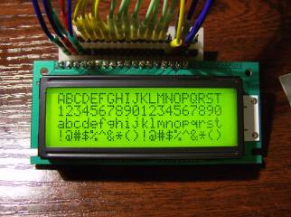
This is a C-library for avr-gcc/avr-libc to access SED1520-based graphics-LCDs. The drivers has the same features as the SED1520.
For some strange reason the suppliers of LCD displays provide terrible documentation for their products. This can turn using one of these otherwise excellent devices into a tedious exercise as you guess how to make the thing work.
This section provides documentation for the SG12232A graphic LCD display and presents driver software that can be incorporated in a microcontroller project.
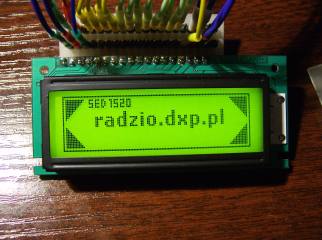
This display is a monochrome 122 x 32 pixel display with a backlight. In Australia the retailer is Altronics altronics.com.au who sell it as Dotmatrix LCD 132 x 32 Backlit part number Z7052. Note that despite the title, it is only 122 pixels wide.
It is also sold under the part number SG12232AULB-GS-K and is part of the Sunlike Display series from Global Elecom Corp. The display uses the SED1520 controller chip from S-MOS Systems Inc so you might find this section useful if you have a different display using that chip.
Altronics provide the most minimal documentation in a short datasheet. However, a more helpful user manual is available from the download section at the bottom of this page.
If you want to delve into the details of the SED1520 controller chip, you can also find its data in the download section.
This discussion will not repeat any of this documentation. However, it will try to illuminate some of the obscure aspects not properly covered.
The LCD communicates over an 8 bit bus and you have four types of communication:
Reading a byte from the buffer memory
Writing a byte to the buffer memory
Reading and writing is selected by the R/W pin. Accessing the buffer memory or status/command is controlled by the Ao pin. The following table lists the signals and their function. They are all outputs from the microcontroller to the LCD, with the only exception being the data bus which is an input when R/W is high.
Supply voltage of 5V Vdd is positive
Clock input. Annoyingly this display requires a square wave signal to make the LCD glass work. The frequency can be anywhere between 3KHz and 50KHz with 4KHz seemingly the optimum.
LCD Glass voltage. This is a negative voltage with respect to the supply voltage Vdd and should be about 4.9V negative. Varying this voltage changes the contrast. With a 5V or greater supply this can be provided by a 20K potentiometer between Vdd and Vss with the wiper going to Vo, But, to get full control you need to take Vo greater than 5V negative and that will require generating a voltage that is negative with respect to ground Vss.
Controls reading/writing to the buffer memory when Ao is high, or the control/status register when Ao is low. Should be called D/I Data/Instruction as in other graphics displays.
Selects which chipset the command/data is directed to. The signal is active high. For example, if CS2 is high then any command/data is directed to the second chip.
Enable. This is the data strobe for reading/writing on the bus, it is active high. When writing to the LCD you must have your data on the bus before you take E high and you must keep it there until after you lower it. When reading, the LCD will place its data on the bus about 100nS after E going high.
Read/Write. When high the LCD module will take control of the bus and place its data on it. When low you have control of the bus and can place data on it. Obviously you must also change the direction of the I/O port on your microcontroller when you manipulate R/W.
Reset signal, pulling it low holds the LCD in reset. Can be permanently wired to 5V
Power to the backlight A is positive. Do not connect to 5V, use a resistor to limit the current.
The pin numbers for these signals are given in the documentation. Note that the normal orientation of the display is with the connector at the top and in that case pin 1 is the most left hand pin.
The display employs 2 controller chips. Chip 1 selected by CS1 controls the left hand side of the display i.e. pixels 0 to 61 wide and 32 pixels high while chip 2 selected by CS2 controls the right hand side of the display i.e. pixels 62 to 121 wide and 32 pixels high. The buffer memory for each chip is organised as an array 62 bytes wide and 4 bytes high i.e 62 columns by 4 rows. Each byte represents 8 vertical pixels with bit zero representing the top pixel. Because there are 4 rows with 8 pixels in each row you end up with a display 32 pixels high.
A driver for the SG12232A is available from the download section at the bottom of this page. This was written for the PIC microcontroller family and will work with the CCS C compiler tested and should work with the HiTech C compiler not tested.
It is an include file that should be included in your main c file and it provides three usable functions:
Must be called before any other function.
Sets the pixel to the given colour.
Origin x 0, y 0 is top left corner
Colour can be ON or OFF 1 or 0
Fills the entire LCD with the given colour.
This driver can be used with the GLCD_Driver to draw lines, circles and print characters in a variety of fonts. The GLCD_Driver is listed in the download section below.
Having access to documentation and some programming code is often only part of the battle. The remainder can often be fixed by having access to a real world project that actually works using the device.
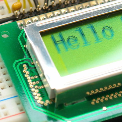
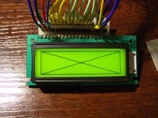
The downloads include a demonstration project program and schematic that uses the SG12232A driver and GLCD_Driver to print Hello World. on the display. Note that the characters are drawn pixel by pixel using the graphics capabilities of the display it does not have a built in character function.
SG12232A LCD Display User Manual
SED1520 Controller Documentation
SG12232A Driver for PIC microcontrollers v1.0
Graphics Driver for PIC microcontrollers and CCS C compiler glcd_driver.h
Demonstration project for the SG12232A LCD Display - Software and schematic
Universal C library for SED1520/NJU6450 LCD This library is designed for LCD displays with SED1520/NJU6450 controller IC and 122x32 pixels resolution.
SED1520 A 2 kHz SED1520 A, The SED1520 series identifies a data bus using a combination of A0 and LCD driver ON resistance RON Ta 25 deg. C kΩ COM0.
SED1520 Series 1 Dot Matrix LCD Controller DriverSSC5000Series PF469-06 SED1520 Series DESCRIPTION The SED1520 family of dot matrix LCD drivers are designed for.
Graphic Dot Matrix LCD module Display driver Library C source display driver library for the SED1520 family of LCD display controllers.
